The motherboard in this build is the first to support the 2.0 GHz Pentium 4 in Socket 478. It features dual-channel RDRAM support, integrated audio, 10 / 100 BaseT networking, and five USB ports. The micro ATX layout only supports three PCI expansion slots (the vertical white slots to the bottom left), but with the integrated features and all those USB ports, that's more than enough for most applications.
The Pentium 4 for Socket 478 is physically smaller than any of the other CPUs currently in use, due largely to the smaller dimensions employed on the silicon level. The chip is keyed to the socket with a missing pin in one corner, so it can’t be inserted the wrong way.
The first step to install the CPU is to lift the locking lever on the side of the socket. Move the lever a little away from the side of the socket to free it from the hold-down, and gently pull it up until stops. It shouldn't require any force to move the locking lever. You can actually lift it with one finger once it's past the hold-down.

The Pentium 4 is placed in the socket with the keyed corner, also marked by the black dot, matching the socket key. The locking lever is lowered back into the tuck position. Don't be surprised by the great change in resistance between raising the lever and lowering it. The lever locks 478 pins in place by spring force.
The Pentium 4 heatsink for Socket 478 actually consists of three pieces. The first of these, the retention module, came permanently mounted on the motherboard. The two pieces shown here are the retention clip and the active heatsink, a fan mounted on a finned aluminum structure that maximizes surface area to disperse the heat.

The dark area on the bottom of the heatsink is a pre-applied thermal interface, saving us from the need to apply thermal grease to the CPU package. The retention clip is placed over the heatsink and the whole assembly is lowered into the retention module. The heatsink settles over he CPU, held a slight distance above it by the pads in the corners of the retention module.
The retention clip fits loosely over he heatsink, with its four clips lined up with the four holes in the retention module posts. Push the whole retention mechanism down over the heatsink to lock the individual clips in place. These clips make an audible "click" as they are pushed over the retention module, but the whole assembly sits quite loosely.

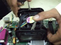
The two levers that force the heatsink into contact with the CPU and lock the whole assembly into place actually move in opposite directions. Lift both levers (I do this simultaneously) and bring them all the way over until they lock down in the opposite positions. This takes even more force than the locking lever on the CPU socket.
As soon as the active heatsink is locked in place, attach the fan to the CPU fan point on the motherboard, normally labeled "fan 1." This allows the motherboard BIOS (Basic Input / Output System) to monitor the CPU fan speed and manage it in power saver and sleep modes. In this instance, the fan 1 connector was the closest connector to the CPU socket, but this isn't always the case, so check your motherboard documentation.


No comments:
Post a Comment